OM-2 Highlights (OM2(n) Website)
The Olympus OM-2 was first seen as a conceptual camera in prototype form at the 1974
Photokina. But it was introduced quite late in 1975 where the same year Canon brought
their immensely successful Canon AE-1 to the market. The OM-2 camera bears a
strong resemblance to the OM-1 but has many very different features. It fact, you
can safely referred the OM-2 as an OM-1 with auto exposure because, when you turn
the mode selector lever to "manual", the OM-2 will operate exactly like
an OM-1 camera - it even has an identical viewfinder display where the familiar match
needle indication is the same. However, once you push the mode selector lever to
'AUTO' the camera will behave and even inside the viewfinder the exposure display
will changed accordingly to exposure mode selected. Some early reviews indicating
reservation over the reliability of such dual display system employed in the camera,
but it proves over time that the OM-2 was indeed a camera designed and made to last.
Despite the fact that it is an automatic-exposure SLR, it shares virtually the same
body dimensions as the OM-1 but is slightly heavier. The few external differences
are mostly confined to the film speed setting dial and the meter system on-off switch
(which the OM-2 has few positions to control).
 |
The metering system employed in the OM-2 is quite unique. It has 2 pairs (four) metering cells to handle the task of metering. The first pair, two CdS sensors as those used in the OM-1 are housed near the eyepiece performing the task as other conventional SLR during that time, reading the exposure and gives an estimate of the shutter speed that will be set by the meter and timed by the electronically-controlled shutter. |
The same CdS sensors indicate the shutter speed which you should set in the manual mode. Basically, the OM-2's automatic exposure determination is made from image-forming light reflected from the film - either through simulated or direct readout method.
The next pair, using Silicon blue cell handle the task differently, they are located inside the mirror box, behind the mounting lens, pointing backward at the film plane or shutter curtain. These two sensors will take over from the CdS cells after the mirror is raised. They measure the light reflected off the film plane OR the first shutter curtain. The shutter curtain of the OM auto SLR cameras (Apply to OM-3 and 4 Ti as well) is printed with computer-generated random digital pattern which simulates an average reflectance of a broad variety of film surfaces.
During an exposure process, it reads light reflected from the film surface until a theoretical optimum exposure is achieved. When sufficient light has reached the film, the electronic circuitry senses the information and instantly closes the shutter. If the light changes after the mirror is raised, or even half way through the exposure, the shutter speed will vary accordingly.
 |
The pattern on the first shutter blind is designed to give a Centre-Weighted reading (OM-2n has an non-publicized upgrade with a slightly well distributed pattern in later years). The meter translates the reading into a value of light intensity at the film surface and adjusts the electronic shutter to a suitable speed to give correct exposure for the film speed set. |
The metering and shutter speed adjustment is continuous while the shutter is open for longer exposures but then most of the reading is taken from the film surface and is not Centre-Weighted Thus, the meter reading in the AUTO mode is taken at the preset user-selected aperture value. A "simulated value" is recommended by the CdS sensors (Such reading is not continuous) and the data is shown in the viewfinder display which act as a reference to the photographer for consideration before the shutter is released.
Why is the metering system being designed so complicated ? Many believe such unique and innovative system was designed so as to avoid Asahi-patented methods which uses memory circuits to store the meter reading after the mirror rises (Of which most SLR system are based upon). Besides, the same pair of blue cells handle the task when operate the OM-2 with a dedicated flash unit such as the T series compact flash for TTL OTF flash exposure control. It was a revolutionary flash system, a pioneer of today's popular TTL flash used in most modern SLRs. Other than operative in AUTO mode, Manual operation is also provided, but unlike the mechanical OM-1, the OM-2 would require a power source to enable the camera to operate, which means it will not be functional without a battery in the camera and the switch set to manual; because the shutter is totally electronically controlled and cannot operate without a battery. However, a thing to note is, when OM2 is shut down, there's no meter or scale at all inside the viewfinder and the "B" setting is purely mechanical.
The metering system is of the aperture-preferred type (you set the aperture and the camera circuitry will select matching shutter speed), Although it is not as convenient as shutter priority AE as used by Canon bodies or some of the Minolta models such as Minolta XD-7/11 but you can still achieve similar result by setting approximately the shutter speed you want just by adjusting the aperture until the speed required shows in the viewfinder. In Automatic mode, the OM-2 is unchallenged even by today's standard - measured exposures cover the range from 1/1000 sec to 60 sec. An interesting feature is that in the automatic mode, the meter is actually a stopped-down type, although you can view the readout at full aperture. Looks like it takes a Olympus to extend such low light metering capability on their original attempts; OM-4 and OM-4Ti can extend the metering range of the record set by OM-2n from 1/2000 sec down to 120 sec in auto mode !
A slight draw back
on the spec sheet for OM-2 is its omission of the useful mirror lockup feature. It
was mysteriously removed from the OM-2 feature list. Although many would question
true functionality and usefulness of a mirror lock up but since the OM-2 bodies has
its TTL OTF metering which may prove to be invaluable in some of the specialized
application such as astrophotography that would require absolute stillness during
exposure. Another more general application is none other than where one of the main
strength of OM-system lies that is the OM Macro photo system. Although in extreme
macrophotography can take advantage of the TTL flash exposure control that comes
with the OM-2n, which in most cases can help to eliminate camera or subject movement
but in a non-flash macrophotography, it is always being an advantage to have mirror
lock up for critically extra-high magnifications. Anyway, the OM bodies are designed
with a very thoughtful self timer operation, once the operation is activated, the
main reflex mirror will flip up before the count down starts, you may still achieve
similar result like a mirror lock up, difference is just being the operation is momentarily
rather than fixed until the lever is turned and return to normal viewing position.
General Remarks - Viewfinder
Ask anyone to give a first impression of an Olympus SLR camera where chances are
high majority would tell you the small body dimension of the OM-1 and OM-2 make its
extra-large magnification projected inside the viewfinder such an amazing experience
but also such a joy to use. The viewfinder for both OM-1 and OM-2 bodies are quite
similar where pentaprism
type wide vision finder id employed. The impressive projection is attributed by the
high viewfinder magnification of 0.92 X (at infinity with 50mm standard lens). Further,
Olympus engineers have managed to retain a highly accurate finder view-field of 97%
of actual picture field (Apparent field view: Vertical 23°30', horizontal 35°)
which is very useful in circumstances where truth of life projection of image is
required.
However, Olympus
never has any of their models provided with a interchangeable viewfinder system but
the focusing screens are interchangeable. OM-1 bodies has a simple to use match needle
indicative system at the bottom left hand section of the viewfinder. The OM-2 finder,
however, has a more complicated readout. In
automatic mode, a colorful shutter speed meter moved into place (See below for comparison).
The needle
indicates the shutter speed which will be set in the automatic mode or acts as a
centering needle in the manual mode just as the OM-1. When the meter is switched
off, only the tip of the needle is visible in the bottom left hand corner of the
screen. The other readouts are removed.
|
|
|


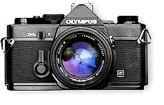
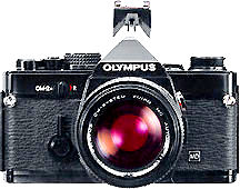
Copyright ©-Free Images collection 2000. leofoo ® Malaysian Internet Resources. <- OM-1n, OM-2 (Manual); OM-2n (AUTO) ->
General Remarks - Accessory Shoe, sync Terminal and Flash synchronization
Both the OM bodies of OM-1 and OM-2 series have a rather odd design of a removable accessory shoe. The on-camera flash seating on the Olympus OM cameras is in the form of a detachable accessory shoe that screws into the socket on top of the pentaprism.
 |
To attach the accessory shoe, plug it into the socket and turn the toothed wheel in the direction of the arrow. Any flash unit with standard ISO mounting foot can then be mounted in the shoe to synchronize through the electrical contact. Older flash units with cord connection can be still be used via a socket at the side of the camera. |
Although many have given respective reasons pertaining to Olympus decision. but so far non are satisfactory except may be during the launch of the OM-1, Olympus has already prepared and had some of the future design in place for earlier bodies to enable them to enjoy the benefit or after a technical design problem was resolved. Who knows ? Anyway, after the OM-2n, all subsequent OM bodies had their accessory shoe fixed on top of the pentaprism.
 |
Since there were essentially a few upgrades within the OM-1 and OM-2 series bodies, there were also a few of the accessory shoes designed to match and fit into each model for certain specific task or enhanced feature when used in particularly with a dedicated T-series flash unit. |
Basically, despite the OM-cameras had enjoyed such a fine reputation with their flash photography over the years, the detachable accessory shoe is one small area that would considered a drawback in its design relative to compatibility issues with various combinations of bodies/Flash units.
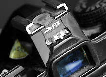
Generally, there were four types of such clip-and screw-on hotshoe. However, the OM-1MD that belongs to my friend Dr. Ahmad Ikram of Rubber Research Institute has a shoe that only has a "FiX" word, thus, there may be more versions than what it offers officially (I don't know where did he got this OM-1 from, but he has quite an extensive lab-usages and extremely high magnification experience in photo-microphotography with Olympus SLR cameras and you are encouraged to contact him).
 |
Type 1 shoe comes as an standard for the original M-1 and OM-1 bodies. It is a single contact hotshoe and permitting only either with manual flash control or normal automatic flash. Type 2 shoe came as standard with the early OM-2 bodies where it allows manual, normal auto and the famous camera regulated flash exposure control first seen in the camera via two electrical contacts when used with Olympus exclusively designed Quick Auto flash 310. |
Strangely, the Type 3 Shoe was not meant to work with Quick Auto Flash 310, instead, it was designed for a new series of TTL flash called T-series to be used on older OM-2 bodies. The hotshoe allows TTL OTF flash exposure control as well as a normal automatic flash and naturally, it also permits full manual flash as well. Lastly, Type 4 Shoe came as a standard accessory on all the OM-1n and OM-2n bodies OM-2N with hotshoe 4 sets the shutter speed automatically to 1/60th of a second when it detects a flash via the terminals. It permits manual, normal auto, and TTL OTF flash exposure control with any of the T-series flash units while it also automatically provides viewfinder flash ready light on both of the newer 'OM-Xn' series models.
 |
In the case of OM-2n models, TTL flash direct metering feature can be extended to off camera operation via cable or sync cord with the accessory shoe 4 with a flash connector. Later OM bodies such as OM-4 and 3Ti has a body integrated TTL sync socket and permits direct mounting of TTL sync cable. The only OM-2 models that has such convenient feature is the OM-2 Spot Program that introduced very late in 1984 (In fact, it came after the OM-3 and OM-4). |
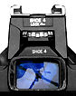
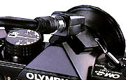
Pictured above is a Flash Connector Type 4 on a OM-2n.
A flash connector ? Yes. It is used to connect a flash unit such as the T32 or T20 to a camera without a connector socket via a TTL Auto Cord T. TTL Auto Connector Type 3 is for OM-2, while Type 4 for both OM-1n ands OM-2n. Another useful accessory for multi TTL flash setup is the TTL auto Multi Connector 3X which permits up to three flash units to be connected to the camera. More ? Possible. Up to 8 or 9 units of TTL flash is possible with auto cord and multi connectors.
| previous | NEXT | 2/4
| Back |
to Main Index Page of OM1(n) & OM2(n)
Olympus
OM-1(n): Main Index Page (5 Parts) | Camera
Operations
(6
Parts)
Specifications: HTML | PDF | Main Reference Map: HTML | PDF (217k)
Olympus
OM-2(n): Main Index Page (6 Parts) | Camera
Operations
(9
Parts)
Specifications: HTML | PDF (48k) Main Reference
Map: HTML | PDF (203k)
Olympus
OM-2SP: Camera Operations | Other Issues
Specifications: HTML | PDF | Main Reference Map: HTML | PDF
Shared
Resources:
Supplementary
Articles:
TTL
Metering,
Depth
of Field,
Shutter
Speed
& Aperture
Motor
Drive and Power Winder: Main Index Page (4 Parts)
Motor Drive 1 | Motor
Drive 2
| Winder 1 | Winder
2
Flash Photography: Main Index Page (4 Parts)
T45 | T32 | T20 | F280 | S20 | Qucik AUTO 310 | QA300,
200, 200S
Macro-Photography: Main Index Page (3 Parts)
Manual for Photomicro Group (3 Parts) NEW upload !
Macro Flash Units: T10 Ring Flash, T28 Twin, T28 Single,
T8 Ring Flash
Accessories: Databack 1-4 | Screens | Finder Accessory | Remote | Cases
Zuiko Lenses: UPLOADED !!
| Message Board | for
your favourite Olympus
OM-1(n)
and OM-2(n)
series models
| Message Board | for your Zuiko Optics in a shared environment
| Message Board | Specifically for Dispose or Looking for OM Photographic
Equipment
About this photographic site.
Home - Photography in Malaysia |
Copyright
© 2000.
leofoo ®. MIR Web Development Team.
My
old time buddy, Ahmad
Ikram,
Dr of Rubber Research Institute (RRI), Malaysia
who shares the same passion with me and also lending his OM-1n, OM-4 and the Motor
Drive 1 to me for preparing some images in this site. Mr Poon of Foto Poon,
Ipoh, Mr Richard, Ampang Park, Mr Lim and Miss Jenny
of Foto Edar for their generosity for their OM1(n), OM2n camera and some Zuiko lenses.
Mr KKLow for some of his earlier images on the OM-1. Miss Wati and Mirza for helping me to convert
this Operation Manual into a HTML format. Mr MCLau for rectifying some mistakes
made on the earlier preview sites. Site created 'unfortunately' again with a PowerMac
A
personal tribute to the creator of the OM system and also a site dedicated to all
the fans of Olympuses and Zuiko Optics worldwide. Olympus
is a registered tradename of Olympus Inc, Japan.